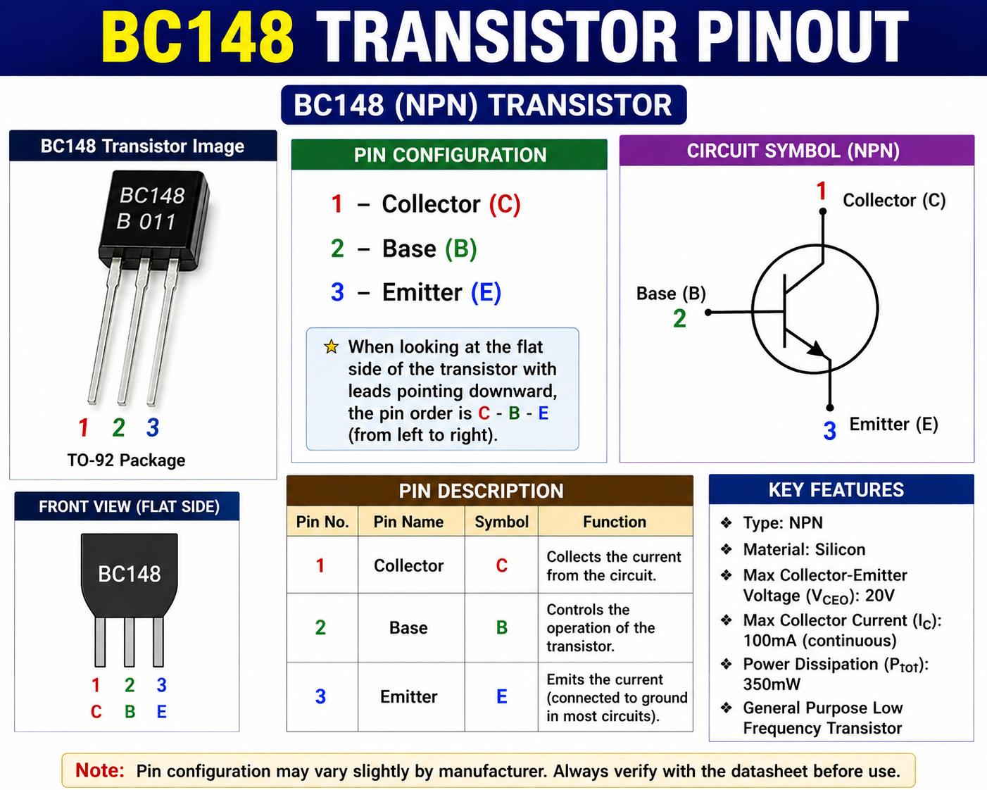
The BC148 transistor is a silicon NPN bipolar junction transistor (BJT) designed for general-purpose and low-frequency electronic applications. It is commonly associated with small-signal amplification, audio circuits, signal processing, driver stages and switching applications.
In this complete BC148 transistor datasheet, we cover the BC148 pinout, transistor symbol, absolute maximum ratings, electrical characteristics, hFE, transition frequency, working principle, applications, equivalent transistors, advantages, limitations and frequently asked questions
Important: BC148 is an older transistor type, and specifications can vary between manufacturers and versions. The numerical specifications in this article are based primarily on the historical Mullard BC147/BC148/BC149 datasheet. Always check the datasheet of the exact device before using it in a production circuit.
BC148 Transistor Quick Specifications
| Parameter | BC148 |
|---|---|
| Transistor Type | NPN |
| Device Type | Bipolar Junction Transistor (BJT) |
| Material | Silicon |
| Application | General Purpose / Low Frequency |
| Package | TO-92 / plastic variants |
| Collector-Emitter Voltage (VCEO) | 20 V |
| Collector-Base Voltage (VCBO) | 30 V |
| Emitter-Base Voltage (VEBO) | 5 V |
| Collector Current | 100 mA in some common versions; historical Mullard data lists 200 mA peak/maximum current rating |
| Power Dissipation | About 250–350 mW depending on manufacturer/version |
| DC Current Gain (hFE) | Up to about 900 in historical specifications |
| Transition Frequency (fT) | Typically around 300 MHz |
| Polarity | NPN |
| Main Use | Amplifier and switching applications |
Historical BC148 references show VCEO = 20 V, VCBO/V CES around 30 V, VEBO = 5 V and fT around 300 MHz. Current ratings and power dissipation vary among versions, so the exact manufacturer’s datasheet should take precedence.
BC148 Transistor Datasheet Table
For quick reference:
| Specification | Value |
|---|---|
| Part Number | BC148 |
| Type | NPN |
| Material | Silicon |
| VCES | 30 V |
| VCEO | 20 V |
| VEBO | 5 V |
| IC | 100 mA |
| ICM | 200 mA |
| IB | 50 mA |
| Ptot | 350 mW |
| Tj max | 125°C |
| Tstg | -65 to +125°C |
| hFE | 125–900 |
| fT | 300 MHz typical |
| Collector Capacitance | 2.5 pF typical |
| Emitter Capacitance | 9 pF typical |
| Main Application | General-purpose low-frequency |
The values above correspond to the referenced historical Mullard data and its specified test conditions.
BC148 Transistor Pinout
The BC148 has three terminals:
- Collector (C)
- Base (B)
- Emitter (E)
A commonly encountered BC148 configuration is Collector–Base–Emitter (C-B-E) when viewed from the specified front/flat side, but pin configuration should be verified against the particular manufacturer’s datasheet, because historical BC148 variants/packages exist.
BC148 Pin Configuration
| Pin | Name | Function |
|---|---|---|
| Pin 1 | Collector | Collects the amplified/switching current |
| Pin 2 | Base | Controls collector current |
| Pin 3 | Emitter | Provides the current return path |
How to Identify the Pins
Do not identify BC148 pins solely from the transistor’s physical appearance. Package drawings from different manufacturers should be checked before soldering the device into a circuit.
What is BC148 Transistor?
BC148 is a small-signal silicon NPN transistor designed primarily for low-level and general-purpose amplification applications.
It can be used as:
- Audio amplifier
- Preamplifier
- Signal amplifier
- Driver transistor
- Switching transistor
- Oscillator circuit
- Sensor interface
- Small electronic projects
The historical Mullard documentation specifically describes BC148 as a general-purpose low-frequency transistor, while related BC147 and BC149 devices were targeted more toward driver and low-noise input applications.
BC148 Transistor Working Principle
BC148 works on the basic principle of an NPN bipolar junction transistor.
It has three semiconductor regions:
N-type → P-type → N-type
These form:
Collector → Base → Emitter
The base is very thin compared with the collector and emitter regions.
A small current applied to the base controls a much larger current flowing between the collector and emitter.
The basic relationship is:
IC ≈ β × IB
Where:
- IC = Collector current
- IB = Base current
- β = DC current gain / hFE
For example, if a transistor has a current gain of 200 and the base current is 0.1 mA:
IC ≈ 200 × 0.1 mA
IC ≈ 20 mA
This is why an NPN transistor can be used for both amplification and switching.
BC148 as an Amplifier
When BC148 is operated in its active region, a small signal at the base can produce a larger signal at the collector.
A typical common-emitter amplifier contains:
- BC148 transistor
- Collector resistor
- Base bias resistors
- Emitter resistor
- Coupling capacitors
- Supply voltage
The transistor’s operating point is established using the bias network. The input signal is then applied to the base, and the amplified signal is obtained from the collector.
BC148 was historically intended for low-frequency/general-purpose amplifier applications, making it suitable for small-signal audio and signal-processing circuits.
BC148 as a Switch
BC148 can also be operated as an electronic switch.
It mainly has three operating regions:
1. Cut-Off Region
When sufficient base current is not supplied:
IC ≈ 0
The transistor behaves approximately like an OFF switch.
2. Active Region
The transistor operates as an amplifier.
3. Saturation Region
When sufficient base drive is applied, the transistor turns strongly ON and behaves approximately like a closed switch.
For small electronic circuits, this makes BC148 useful for controlling LEDs, small loads, signal paths and other low-current circuits, provided its voltage/current ratings are not exceeded.
BC148 Absolute Maximum Ratings
A commonly referenced historical BC148 specification gives the following values:
| Parameter | Symbol | Typical Historical Rating |
|---|---|---|
| Collector-Base Voltage | VCBO | 30 V |
| Collector-Emitter Voltage | VCEO | 20 V |
| Emitter-Base Voltage | VEBO | 5 V |
| Collector Current | IC | 100–200 mA depending on version/rating definition |
| Power Dissipation | Ptot | 250–350 mW depending on version |
| Junction Temperature | Tj | Up to about 125°C in historical data |
| Transition Frequency | fT | Approximately 300 MHz |
For example, a historical Mullard BC147/BC148/BC149 datasheet lists BC148 VCES = 30 V, VCEO = 20 V, ICM = 200 mA, Ptot = 350 mW and Tj = 125°C
Another historical transistor table lists BC148 with 30 V collector-base voltage, 20 V collector-emitter voltage, 5 V emitter-base voltage, 100 mA collector current and 350 mW power dissipation.
Therefore, for a website datasheet, it is better to state the manufacturer/version alongside the ratings rather than presenting every BC148 variant as having exactly the same specifications.
BC148 Thermal Characteristics
The transistor’s power dissipation depends on ambient temperature and thermal conditions.
The referenced Mullard data gives a thermal resistance of approximately:
Rth(j-a) = 0.275 °C/mW
for the specified mounting conditions.
As transistor power dissipation increases, junction temperature also increases.
Therefore, the transistor should be operated within its specified power and temperature limits.
BC148 Electrical Characteristics
The following electrical characteristics are based on the historical Mullard specification.
| Parameter | Test Condition | Min. | Typ. | Max. | Unit |
|---|---|---|---|---|---|
| Collector Cut-off Current | VCB = 20 V, IE = 0 | — | — | 5.0 | µA |
| Collector Cut-off Current | VCE = 20 V, IB = 0 | — | — | 0.6 | µA |
| Base-Emitter Voltage | IC = 2 mA, VCE = 5 V | 550 | 620 | 700 | mV |
| Collector-Emitter Saturation Voltage | IC = 10 mA, IB = 0.5 mA | — | 90 | 250 | mV |
| Collector-Emitter Saturation Voltage | IC = 100 mA, IB = 5 mA | — | 200 | 600 | mV |
| Base-Emitter Saturation Voltage | IC = 10 mA, IB = 0.5 mA | — | 700 | — | mV |
| Base-Emitter Saturation Voltage | IC = 100 mA, IB = 5 mA | — | 900 | — | mV |
| Collector Knee Voltage | IC = 10 mA | — | 300 | 600 | mV |
These values are test-condition dependent and should not be treated as fixed values for every BC148 transistor.
BC148 DC Current Gain (hFE)
The hFE or DC current gain indicates how much collector current can be controlled by a given base current.
Historical BC148 data gives:
hFE = 125 to 900
under specified test conditions, including IC = 2 mA and VCE = 5 V.
The actual hFE of an individual transistor can vary considerably. Therefore, hFE should not be treated as a fixed value.
BC148 Transition Frequency
The transition frequency, fT, is an important parameter for transistor frequency performance.
For BC148, historical data gives approximately:
fT = 300 MHz typical
under specified test conditions.
However, this does not mean that a BC148 should automatically be used as a 300 MHz amplifier. Actual circuit performance depends on bias, load, PCB layout, parasitic capacitance and the particular transistor.
BC148 Collector Capacitance
The referenced Mullard electrical data specifies collector capacitance approximately as:
Cc = 2.5 pF typical
with a maximum value of:
4.5 pF
under the specified test conditions.
Collector capacitance becomes important in high-frequency circuit design because transistor capacitances affect frequency response and signal gain.
BC148 Emitter Capacitance
The referenced data gives:
Emitter capacitance ≈ 9.0 pF
under the specified test conditions.
The internal capacitances of a transistor are important when analyzing its high-frequency behavior.
BC148 Noise Figure
Noise figure is particularly important in low-level amplifier circuits.
For BC148, the historical Mullard documentation specifies noise figure values under particular test conditions, including approximately:
2 dB typical and 10 dB maximum
at:
- IC = 0.2 mA
- VCE = 5 V
- Source resistance = 2 kΩ
- Frequency = 1 kHz
- Bandwidth = 200 Hz
How Does BC148 Transistor Work?
BC148 is an NPN bipolar junction transistor.
A small current at the base controls a larger current between the collector and emitter.
The transistor can operate in three major regions.
1. Cut-Off Region
In the cut-off region, base current is very small or absent.
The transistor is essentially:
OFF
This operating mode is useful in switching circuits.
2. Active Region
In the active region, BC148 operates as an amplifier.
A change in base current produces a corresponding change in collector current.
3. Saturation Region
In saturation, the transistor is strongly ON.
This operating region is commonly used when BC148 is functioning as a switch.
BC148 Applications
BC148 can be used in many small-signal electronic circuits.
Common applications include:
- Audio preamplifier
- Small-signal amplifier
- Low-frequency amplifier
- Signal processing
- Driver stage
- Transistor switch
- Oscillator
- Sensor circuits
- Electronic hobby projects
- Alarm circuits
- LED driver circuits
- Signal conditioning circuits
Historical documentation describes BC148 as suitable for low-voltage applications including driver stages, audio preamplifiers and signal-processing circuits.
BC148 as an Amplifier
BC148 can be used as a small-signal amplifier.
A common-emitter amplifier typically contains:
- BC148 transistor
- Collector resistor
- Emitter resistor
- Base bias resistors
- Input coupling capacitor
- Output coupling capacitor
- DC supply
The input signal is applied to the base. The transistor then produces an amplified signal at the collector.
BC148’s original intended application as a general-purpose low-frequency transistor makes it suitable for many small-signal amplifier circuits.
BC148 Common Emitter Amplifier
A basic common-emitter amplifier can be represented as:
Input → Coupling Capacitor → Base
Collector → Collector Resistor → VCC
Emitter → Emitter Resistor → Ground
Collector → Output Coupling Capacitor → Output
The exact resistor and capacitor values must be calculated according to the desired gain, supply voltage, collector current, operating point and load.
BC148 as a Switch
BC148 can also operate as an electronic switch.
When Base Current Is Low
The transistor remains in cut-off:
BC148 = OFF
When Sufficient Base Current Is Applied
The transistor enters saturation:
BC148 = ON
A suitable base resistor should be used to control the base current.
BC148 should only be used for loads that remain within its voltage, current and power ratings.
BC148 Transistor Advantages
Some important advantages of BC148 include:
- NPN transistor
- Silicon semiconductor
- Small size
- Low-cost general-purpose device
- Suitable for small-signal amplification
- Useful for low-frequency applications
- Can be used as an electronic switch
- High current gain in some versions
- Suitable for many hobby and educational circuits
BC148 Limitations
BC148 should not be considered a high-power transistor.
It is intended for small-signal applications, so it should not be used directly for:
- High-power motors
- High-current relays
- Large lamps
- High-power audio output stages
- High-current loads
For higher-current applications, a suitable power transistor or MOSFET should be selected.
BC148 Equivalent and Replacement Transistors
Possible replacement candidates may include other small-signal NPN transistors such as:
- BC547
- BC548
- BC107
- BC108
- BC238
- 2N3904
However, these should not be treated as direct drop-in replacements without checking the specifications and pin configuration.
For example, BC148 and BC547 may have different voltage, current, gain and package/pinout characteristics depending on the exact version.
Always compare VCEO, IC, Ptot, hFE, package and pinout before replacing a transistor.
BC148 vs BC547
| Feature | BC148 | BC547 |
|---|---|---|
| Type | NPN | NPN |
| Material | Silicon | Silicon |
| Main Use | General purpose / low frequency | General purpose / low-noise |
| VCEO | 20 V historical rating | Common versions 30 V |
| IC | Version dependent | Common versions 100 mA |
| Package | Historical TO-92/plastic variants | TO-92 |
| fT | ~300 MHz historical | Often ~300 MHz |
| Replacement | Check specifications | Check specifications |
BC547 is often easier to source today, but it should not automatically be considered a pin-compatible replacement for every BC148.
BC148 Circuit Example
A simple BC148 common-emitter amplifier can contain:
- BC148 transistor
- 9 V DC supply
- Collector resistor
- Base bias resistors
- Emitter resistor
- Input coupling capacitor
- Output coupling capacitor
The input signal is applied through a coupling capacitor to the base. The transistor amplifies the signal and the amplified output is obtained from the collector through another coupling capacitor.
BC148 Transistor Precautions
When working with BC148, follow these precautions:
- Check the transistor pinout before connecting it.
- Do not exceed the maximum collector-emitter voltage.
- Do not exceed the maximum collector current.
- Avoid exceeding the transistor’s power dissipation rating.
- Do not exceed the emitter-base voltage rating.
- Use an appropriate base resistor when using BC148 as a switch.
- Check the exact manufacturer’s datasheet for the transistor you have.
- Avoid excessive heat during soldering.
- Do not connect the transistor directly across a high-current supply.
- When replacing BC148, verify the replacement transistor’s pin configuration.
BC148 Datasheet Summary
BC148 is a silicon NPN general-purpose transistor designed mainly for small-signal and low-frequency applications. Its historical specifications include a 20 V maximum collector-emitter voltage, 30 V collector-base rating, 5 V emitter-base rating and approximately 300 MHz typical transition frequency. Depending on the manufacturer/version, collector-current and power-dissipation specifications can differ.
Because BC148 is an older component family, the exact datasheet for the manufacturer and package marking should always be used for final circuit design.
How to Test BC148 Transistor with a Multimeter
The BC148 transistor is a silicon NPN bipolar junction transistor (BJT) commonly used in small-signal amplification, audio circuits, switching applications, and other low-power electronic circuits. If you have an old or unknown BC148 transistor, you can check whether it is working properly by using a digital multimeter in diode test mode.
Testing a transistor with a multimeter is a simple and useful technique for identifying a good transistor, a shorted transistor, or an open/damaged transistor.
In this guide, you will learn how to test a BC148 transistor with a digital multimeter, how to identify the Base, Collector and Emitter terminals, what voltage readings to expect, and how to determine whether the transistor is good or faulty.
Important: Always verify the exact BC148 pin configuration from the datasheet of the manufacturer of your transistor before testing it. BC148 versions and historical packages can differ.
BC148 Transistor Quick Information
The BC148 is a silicon NPN transistor designed primarily as a general-purpose low-frequency transistor. Historical Mullard documentation lists the BC148 with a maximum VCEO of 20 V, maximum collector current of 100 mA in its limiting values, and maximum total power dissipation of 350 mW at an ambient temperature of 25°C.
| Parameter | BC148 |
|---|---|
| Transistor Type | NPN |
| Semiconductor | Silicon |
| Terminals | Base, Collector, Emitter |
| Maximum VCEO | 20 V* |
| Maximum VCB/VCES | 30 V* |
| Maximum Collector Current | 100 mA* |
| Maximum Power Dissipation | 350 mW* |
| Junction Temperature | 125°C* |
| Typical Base-Emitter Voltage | About 0.62 V |
| Testing Method | Diode Test Mode |
*Values depend on the particular manufacturer and datasheet version. The table above refers primarily to historical Mullard specifications.
What Do You Need to Test a BC148?
You only need a few things:
- BC148 transistor
- Digital multimeter
- Test leads/probes
- A clean working surface
A separate power supply is not required when checking the transistor’s junctions with the diode-test function.
Why Use Diode Mode to Test a BC148?
A bipolar transistor contains two semiconductor junctions:
- Base-Emitter junction
- Base-Collector junction
An NPN transistor can therefore be tested approximately like two diodes connected to a common Base.
When the digital multimeter is placed in diode mode, it applies a small test current through the semiconductor junction and displays the forward voltage.
For a silicon transistor, a healthy forward-biased junction commonly produces a reading around 0.55 V to 0.75 V, although the exact value can vary with the device, test current and temperature.
The historical Mullard specification gives a BC148 base-emitter voltage of approximately 0.55–0.70 V at IC = 2 mA and VCE = 5 V, with a typical value of about 0.62 V.
Step 1: Identify the BC148 Pins
Before connecting the multimeter probes, you must identify the three transistor terminals:
- Base (B)
- Collector (C)
- Emitter (E)
Do not assume the pin arrangement only from the physical appearance of the transistor.
Different BC148 manufacturers and package versions may have different physical arrangements. Historical Mullard documentation describes the BC148 in a plastic package, while other versions are sold in different package forms.
Important Pinout Warning
Always check the datasheet for the exact BC148 you have.
For example, if your particular transistor is identified as:
Pin 1 = C
Pin 2 = B
Pin 3 = E
then use that configuration during the test.
If your manufacturer’s datasheet specifies a different arrangement, follow that datasheet instead.
Step 2: Set the Multimeter to Diode Mode
Turn on your digital multimeter.
Set the rotary selector to the diode test symbol (→| or diode symbol).
Do not use resistance mode for the main transistor junction test if your multimeter has a diode-test function.
Multimeter Connections
Connect:
- Red probe → V/Ω/diode socket
- Black probe → COM socket
The display may show OL, 1, or another over-range indication when no conducting junction is present.
Step 3: Test the Base-Emitter Junction
For an NPN transistor, the Base-Emitter junction should conduct when the Base is positive relative to the Emitter.
Connect:
Red probe → Base
Black probe → Emitter
A good silicon BC148 should normally show a forward-voltage reading in the approximate range of:
0.55 V to 0.75 V
For example:
0.62 V
would be a normal-looking result.
Result
| Meter Reading | Possible Condition |
|---|---|
| About 0.55–0.75 V | Base-Emitter junction likely good |
| 0.00 V or very low | Possible short |
| OL | Possible open junction or wrong pin identification |
| Very unusual reading | Check pinout and transistor condition |
Remember that the exact reading is not a single fixed number.
Step 4: Reverse-Test the Base-Emitter Junction
Now reverse the probes.
Connect:
Red probe → Emitter
Black probe → Base
A good Base-Emitter junction should now be reverse biased.
The multimeter should normally show:
OL / Over Range
or a very high reading.
If the multimeter shows approximately 0 V in both directions, the Base-Emitter junction may be shorted.
Step 5: Test the Base-Collector Junction
Now test the second internal semiconductor junction.
Connect:
Red probe → Base
Black probe → Collector
A healthy NPN transistor should show a forward-voltage reading, commonly around:
0.55 V to 0.75 V
For example:
0.61 V
can indicate a normal forward-biased Base-Collector junction.
Step 6: Reverse-Test the Base-Collector Junction
Reverse the probes:
Red probe → Collector
Black probe → Base
The meter should normally display:
OL
because the Base-Collector junction is now reverse biased.
If you obtain a very low voltage in both directions, the junction may be shorted.
Step 7: Test Collector to Emitter
Finally, test the Collector-Emitter path.
Connect:
Red probe → Collector
Black probe → Emitter
Then reverse the probes:
Red probe → Emitter
Black probe → Collector
For a normal transistor tested out of circuit, both directions should generally show OL or a very high reading when using diode mode.
This is an important test because a short between Collector and Emitter is a common indication of a damaged transistor.
BC148 Multimeter Test Table
The following table provides a simple testing sequence.
| Test | Red Probe | Black Probe | Expected Reading |
|---|---|---|---|
| 1 | Base | Emitter | About 0.55–0.75 V |
| 2 | Emitter | Base | OL |
| 3 | Base | Collector | About 0.55–0.75 V |
| 4 | Collector | Base | OL |
| 5 | Collector | Emitter | OL |
| 6 | Emitter | Collector | OL |
These readings are typical diagnostic expectations rather than absolute pass/fail limits. Actual readings can vary with the transistor and multimeter.
How to Know If the BC148 Is Good?
A BC148 is likely to be good when:
- Base-to-Emitter shows a normal forward voltage.
- Base-to-Collector shows a normal forward voltage.
- Reversing those two tests gives OL/high resistance.
- Collector-to-Emitter does not show a near-zero short in either direction.
For example:
B → E = 0.62 V
E → B = OL
B → C = 0.61 V
C → B = OL
C → E = OL
E → C = OL
This pattern is consistent with a normal NPN transistor.
How to Identify a Shorted BC148
A BC148 may be faulty if the multimeter shows approximately:
0.00 V or a very low reading
between terminals where a reverse-biased junction should block current.
For example:
Base → Emitter = 0.02 V
and
Emitter → Base = 0.01 V
would strongly suggest an abnormal/shorted junction.
Similarly, if Collector and Emitter show almost zero voltage in both directions, the transistor may have a Collector-Emitter short.
How to Identify an Open BC148
A transistor may be open or damaged if the expected forward-biased Base-Emitter and Base-Collector junctions both show:
OL
For example:
B → E = OL
B → C = OL
This can indicate an open transistor.
However, before declaring the transistor faulty, check the following:
- Correct pin identification
- Correct multimeter mode
- Probe connections
- Clean transistor leads
- Whether the transistor is completely removed from the circuit
Very Important: Test the Transistor Outside the Circuit
For the most reliable result, remove the BC148 from the circuit before testing.
Testing a transistor while it is still soldered into a circuit can produce incorrect readings because other components may be connected between the transistor terminals.
For example, resistors, diodes, capacitors and other semiconductor devices connected to the transistor can affect the multimeter reading.
Best Practice
Remove the BC148 from the circuit → identify its pins → select diode mode → perform all junction tests.
Can a BC148 Be Tested Without Removing It?
Yes, you can perform a quick in-circuit check, but the result may not be conclusive.
If you get an unexpected reading, remove the transistor from the circuit and test it separately.
This is especially important when the circuit contains:
- Resistors
- Diodes
- Capacitors
- Integrated circuits
- Other transistors
- Transformer windings
Common BC148 Testing Problems
1. Multimeter Shows 0.00 V
A 0 V or extremely low reading in both directions can indicate a shorted semiconductor junction.
However, first verify that the probes are connected to the correct pins.
2. Multimeter Shows OL Everywhere
If every combination shows OL, possible causes include:
- Wrong pin identification
- Open/damaged transistor
- Poor contact with transistor leads
- Dirty or oxidized leads
Clean the leads and repeat the test.
3. Reading Is Around 0.80 V
A reading slightly above the commonly expected range does not automatically mean the transistor is bad.
Forward voltage depends on test current, temperature and device characteristics.
The best approach is to compare all six tests rather than judging the transistor from one number.
4. Different Readings on Different Multimeters
Different digital multimeters use different diode-test currents and measurement circuits.
Therefore, two meters may not display exactly the same forward voltage.
The important point is to identify the overall junction behavior.
BC148 Testing Using Resistance Mode
If your multimeter does not have a diode-test function, you can perform a basic resistance test.
Set the meter to resistance mode and test:
- Base to Emitter
- Emitter to Base
- Base to Collector
- Collector to Base
- Collector to Emitter
- Emitter to Collector
A good transistor should show different resistance behavior depending on the direction of the probes.
However, diode mode is generally easier and more informative for checking a silicon BJT.
Difference Between a Good and Bad BC148
| Condition | Good BC148 | Faulty BC148 |
|---|---|---|
| B-E forward test | Forward voltage | OL or very low/short |
| B-E reverse test | OL/high | Low reading may indicate short |
| B-C forward test | Forward voltage | OL or very low/short |
| B-C reverse test | OL/high | Low reading may indicate short |
| C-E test | Usually OL both directions | Low reading may indicate C-E short |
| Overall result | Normal diode-junction behavior | Abnormal readings |
Precautions While Testing BC148
Follow these precautions for reliable testing:
1. Remove Power
Never test a transistor in a powered circuit.
Switch off the power supply before connecting the multimeter.
2. Remove the Transistor When Possible
For accurate testing, remove the BC148 from the circuit.
3. Use Diode Mode
Use the diode-test function of a digital multimeter.
4. Verify the Pinout
Do not assume the pin order from another transistor such as BC547 or BC548.
Check the exact BC148 datasheet.
5. Do Not Apply External Power
A normal diode-mode transistor test does not require an external power supply.
6. Avoid Excessive Heat
Do not hold a soldering iron on the transistor leads for too long when removing the component.
7. Clean the Leads
Dirty or oxidized transistor leads can produce unreliable readings.
Conclusion
Testing a BC148 transistor with a digital multimeter is a simple way to determine whether its internal semiconductor junctions are behaving normally.
The basic method is:
Identify the pins → Set the multimeter to diode mode → Test Base-Emitter → Test Base-Collector → Reverse the probes → Test Collector-Emitter → Compare the readings.
A good NPN transistor normally shows a forward voltage across the Base-Emitter and Base-Collector junctions and a blocking/OL indication when those junctions are reverse biased.
For the most reliable result, always test the BC148 outside the circuit and verify the exact pin configuration from the manufacturer’s datasheet.
BC148 Transistor FAQs
What is BC148?
BC148 is a silicon NPN bipolar junction transistor mainly used for general-purpose and low-frequency small-signal amplification.
Is BC148 an NPN or PNP transistor?
BC148 is an NPN transistor.
What is the maximum voltage of BC148?
A commonly referenced historical specification gives 20 V VCEO and 30 V collector-base voltage.
What is the maximum current of BC148?
The rating depends on the manufacturer/version. Historical data includes 100 mA continuous-style ratings and 200 mA ICM in some older specifications. Therefore, the exact manufacturer’s datasheet should be checked.
Is BC148 a transistor or diode?
BC148 is a transistor, specifically a silicon NPN BJT.
Can BC148 be used as a switch?
Yes. It can be used as a small-signal electronic switch when operated between cut-off and saturation.
Can BC148 be used as an amplifier?
Yes. It is particularly associated with general-purpose and low-frequency amplification applications.
How do I test a BC148 transistor with a multimeter?
Set the digital multimeter to diode mode. Identify the Base, Collector and Emitter pins from the correct datasheet. For an NPN transistor, test Base-to-Emitter and Base-to-Collector in the forward direction. You should normally see a silicon-diode-like forward voltage. Reverse the probes and check that the reverse-biased junctions show OL.
What voltage should a good BC148 show on a multimeter?
A healthy silicon BC148 junction commonly shows approximately 0.55 V to 0.75 V in a forward-biased diode test. Historical Mullard data gives approximately 0.55–0.70 V for the Base-Emitter voltage under its specified test conditions, with 0.62 V typical.
How do I know if my BC148 is bad?
If the Base-Emitter or Base-Collector junction reads almost zero in both directions, the transistor may be shorted. If the expected forward junction tests always show OL, the transistor may be open. However, verify the pinout and test the transistor outside the circuit before concluding that it is faulty.
Can I test BC148 using a digital multimeter?
Yes. A digital multimeter with a diode-test function is one of the easiest tools for performing a basic BC148 transistor junction test.
Should I remove the BC148 from the circuit before testing?
Yes. Removing the transistor from the circuit gives a much more reliable result because surrounding components can affect the multimeter readings.
Is BC148 an NPN or PNP transistor?
BC148 is an NPN silicon transistor. Historical Mullard documentation describes the BC148 as a general-purpose low-frequency NPN transistor.
Can a multimeter test transistor gain?
Some digital multimeters have an hFE socket or transistor-test function. However, a basic diode test primarily checks the transistor’s semiconductor junctions; it does not provide a complete characterization of transistor performance