Single Diode Rectifier Circuit with Transformer and Filter
Learn about the Single Diode Rectifier Circuit with Transformer and Filter, including its circuit diagram, components, working principle, construction method, applications, advantages, and safety precautions.
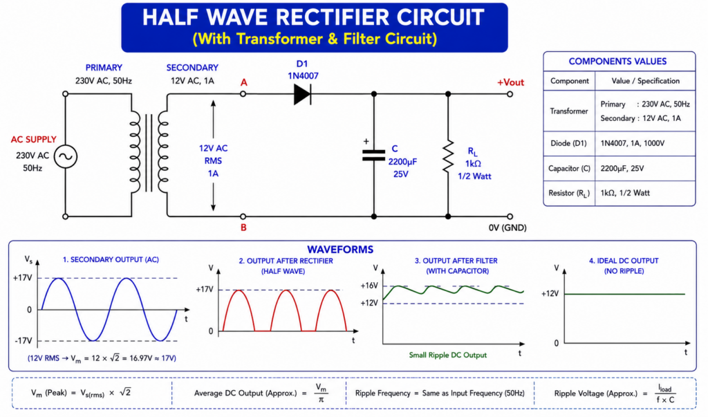
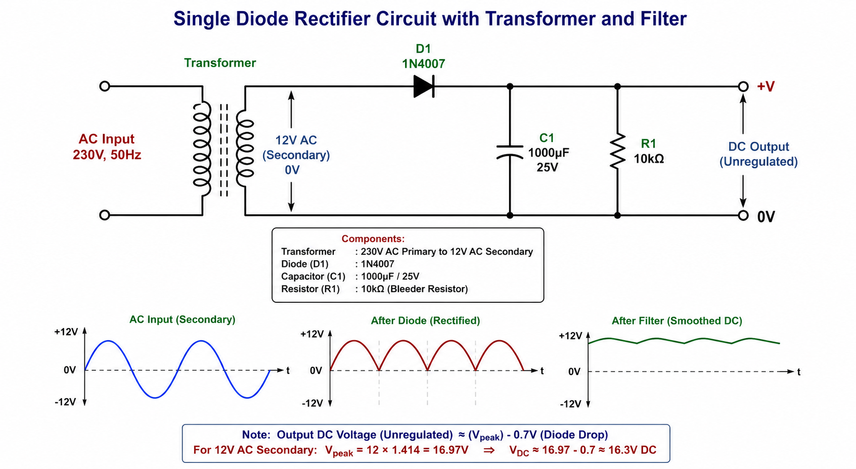
This circuit converts 230V AC into low-voltage, unregulated DC using a transformer, a single diode, and a capacitor filter.
Circuit Components
- Step-down Transformer – 230V AC to 12V AC
- Diode D1 – 1N4007
- Filter Capacitor C1 – 1000µF / 25V
- Resistor R1 – 10kΩ, optional bleeder resistor
- Connecting wires
- Breadboard or PCB
- Multimeter
1. Working Principle of the Circuit
The circuit works in four main stages:
230V AC → Transformer → Diode Rectifier → Capacitor Filter → DC Output
Step 1: AC Input
The circuit receives 230V AC, 50Hz from the mains supply.
The transformer is used to reduce this high voltage to a safer low voltage.
Step 2: Transformer
A 230V/12V step-down transformer converts the 230V AC input into approximately 12V AC at its secondary winding.
The transformer also provides electrical isolation between the mains side and the low-voltage side.
Step 3: Half-Wave Rectification
The 12V AC output is connected to the 1N4007 diode.
The diode allows current to flow mainly during one half-cycle of the AC waveform and blocks the opposite half-cycle.
As a result, the AC waveform is converted into pulsating DC.
This is called half-wave rectification because only one half of the AC cycle is used.
Step 4: Filtering
The rectified output contains significant voltage fluctuations, called ripple.
The 1000µF capacitor is connected across the DC output.
When the diode conducts, the capacitor charges toward the peak voltage. When the diode stops conducting, the capacitor discharges through the load and helps maintain the output voltage.
Therefore, the capacitor converts the pulsating DC into a smoother DC voltage.
Step 5: DC Output
The filtered output can be used as a low-voltage DC source for suitable electronic circuits.
For a 12V AC secondary:
Peak voltage ≈ 12 × 1.414 = 16.97V
After approximately 0.7V diode drop:
Peak filtered voltage ≈ 16.3V DC
The actual voltage under load will be lower and will depend on the transformer, load current, capacitor, and mains voltage.
Important: This is an unregulated DC supply. It should not be treated as a regulated 12V DC output.
2. How to Build the Circuit Step by Step
Step 1: Select the Transformer
Use a suitable 230V AC to 12V AC step-down transformer.
For a beginner project, use a properly rated, enclosed transformer rather than an exposed transformer.
Step 2: Connect the Transformer
Connect the primary winding to the AC mains only if you have the necessary electrical knowledge and safety precautions.
The secondary winding provides approximately 12V AC.
Step 3: Connect the Diode
Connect the 12V AC secondary to the 1N4007 diode.
The diode’s cathode is identified by the stripe/band on the diode body.
Connect the diode so that the rectified output is obtained at the cathode side.
Step 4: Connect the Capacitor
Connect the 1000µF/25V electrolytic capacitor across the rectified DC output.
The capacitor polarity is very important:
- Capacitor + → Diode output / +DC
- Capacitor − → Transformer return / 0V
Never reverse the polarity of an electrolytic capacitor.
Step 5: Connect the Bleeder Resistor
A 10kΩ resistor can be connected across the output.
It acts as a bleeder resistor and provides a discharge path for the capacitor after power is removed.
Step 6: Check the Wiring
Before applying power, carefully check:
- Diode orientation
- Capacitor polarity
- Transformer connections
- Loose wires
- Short circuits
- Correct capacitor voltage rating
Step 7: Test the Output
After safely powering the circuit through the transformer, use a multimeter set to DC voltage to measure the output.
Do not touch the circuit while it is energized.
3. Applications / Uses
A single-diode rectifier with a capacitor filter can be used for:
1. Basic DC Power Supply
It can provide an unregulated DC voltage for simple electronic circuits.
2. Electronics Demonstration
It is commonly used to demonstrate:
- AC to DC conversion
- Rectification
- Diode operation
- Capacitor filtering
- Ripple voltage
3. Educational Projects
It is useful for electronics laboratory experiments and student projects.
4. Low-Power Circuits
It can supply suitable low-current circuits where voltage regulation is not critical.
5. Understanding Power Supplies
It demonstrates the basic stages used in traditional linear power supplies:
Transformer → Rectifier → Filter → Regulator
A regulator stage can be added later if a stable DC voltage is required.
4. Advantages
- Simple circuit
- Low component count
- Easy to understand
- Low-cost components
- Useful for learning rectification
- Provides electrical isolation when a proper isolation transformer is used
- Capacitor reduces output ripple
5. Disadvantages
- Only one half-cycle of AC is utilized.
- Output ripple is higher than a full-wave rectifier.
- Power efficiency is relatively low.
- The output voltage is not regulated.
- A large capacitor may be required for lower ripple.
- The diode and transformer must be correctly rated for the load.
For practical power supplies, a full-wave bridge rectifier is generally more efficient and produces lower ripple than a single-diode half-wave rectifier.
6. Precautions and Safety
The 230V AC mains side is dangerous and can cause severe electric shock, burns, or death.
Important precautions:
- Never work directly on the 230V mains while the circuit is powered.
- Use a properly rated 230V-to-12V isolation step-down transformer.
- Keep the primary/mains section physically separated from the low-voltage section.
- Use proper insulation and an enclosed electrical box for the mains-side connections.
- Do not connect the 12V secondary directly to 230V mains.
- Check the polarity of the electrolytic capacitor before switching on the circuit.
- Use a capacitor with a suitable voltage rating. For a 12V AC secondary, 25V or higher is a practical choice.
- Make sure the diode’s current and reverse-voltage ratings are suitable for the application.
- Do not touch exposed conductors when the circuit is energized.
- Switch OFF and unplug the supply before changing or repairing any connection.
- The capacitor can remain charged after power is removed. Allow it to discharge safely before handling the circuit.
- Do not use this unregulated output to power sensitive electronics unless the voltage and ripple are confirmed to be within their specifications.
- Use a fuse and appropriate protection on the mains input as required by the transformer and installation.
- If you are not experienced with mains electricity, have the 230V wiring performed or checked by a qualified electrician.
7. Important Output Voltage Note
One common mistake is assuming that a 12V AC transformer automatically produces 12V DC after rectification and filtering.
It does not.
For example:
12V AC RMS
Peak voltage:
12 × 1.414 ≈ 16.97V
After a silicon diode drop:
16.97 − 0.7 ≈ 16.27V
So, with a capacitor filter, the no-load output can be around 16V DC, not 12V DC.
Under load, the voltage will normally decrease depending on the transformer regulation, load current, capacitor value, and ripple.
If you specifically need regulated 12V DC, add an appropriate voltage regulator stage after the filter.