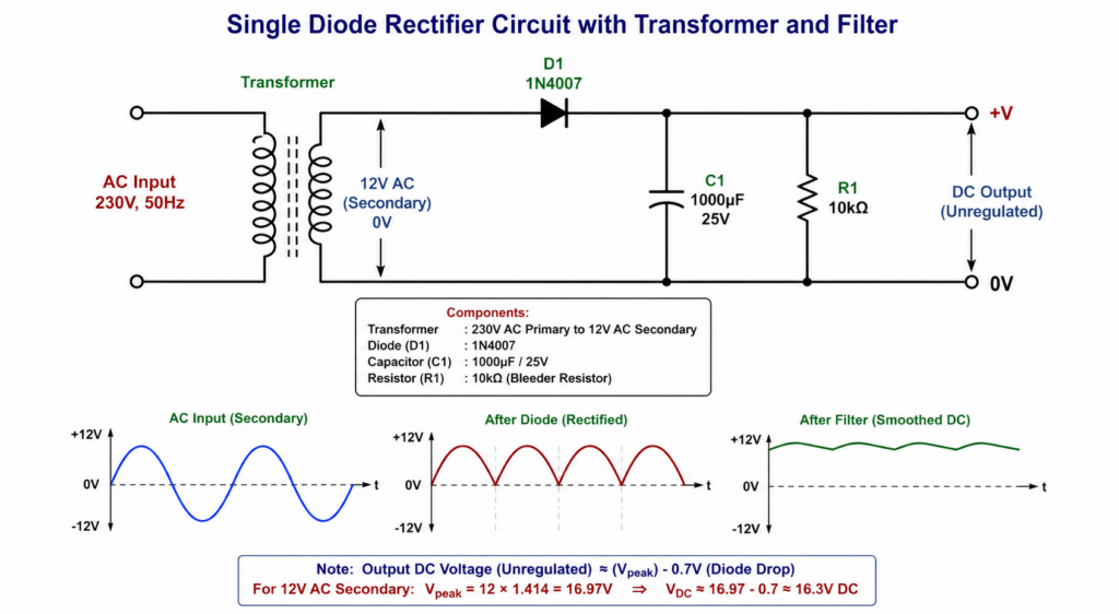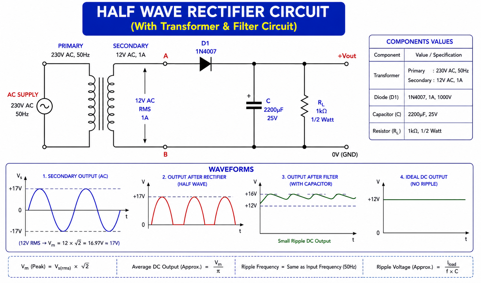
A Half Wave Rectifier is one of the simplest electronic circuits used to convert AC (Alternating Current) into pulsating DC (Direct Current). It uses a diode to allow only one half-cycle of the AC waveform to pass through.
When a capacitor filter is added, the pulsating DC output becomes smoother and more suitable for low-power electronic circuits.
This complete guide explains the Half Wave Rectifier Circuit with Transformer and Capacitor Filter, including its circuit diagram, components, working principle, construction, formulas, waveform, applications, advantages, disadvantages, and safety precautions.
What is a Half Wave Rectifier?
A Half Wave Rectifier is an electronic circuit that converts AC voltage into pulsating DC voltage by allowing only one half-cycle of the AC input to reach the output.
The main component responsible for rectification is the diode.
- During the positive half-cycle, the diode becomes forward biased and conducts current.
- During the negative half-cycle, the diode becomes reverse biased and blocks current.
Therefore, only one half of the AC waveform appears at the output.
When a capacitor is connected across the output, it acts as a filter and reduces the voltage fluctuations or ripple.
Half Wave Rectifier Circuit with Transformer and Filter
The circuit described in this article uses:
230V AC → Step-Down Transformer → 1N4007 Diode → Capacitor Filter → Load Resistor → DC Output
The transformer reduces the 230V AC mains voltage to approximately 12V AC, the diode performs rectification, and the capacitor smooths the rectified output.


Components Required
The circuit shown uses a 12V AC, 1A transformer, 1N4007 diode, 2200µF/25V capacitor, and 1kΩ/0.5W load resistor.
Function of Each Component
1. Transformer
The transformer is used to reduce the high 230V AC mains voltage to a lower AC voltage.
In this circuit:
Primary: 230V AC, 50Hz
Secondary: 12V AC, 1A
The transformer also provides electrical isolation between the mains side and the low-voltage secondary side.
2. Diode – 1N4007
The 1N4007 diode performs the main rectification operation.
It allows current to flow primarily in one direction.
During the positive half-cycle, it conducts.
During the negative half-cycle, it blocks current.
3. Capacitor – 2200µF, 25V
The capacitor works as a filter.
After rectification, the output is pulsating DC. The capacitor charges near the peaks and discharges through the load when the diode is not conducting.
This reduces the voltage variation and produces a smoother DC output.
4. Load Resistor – 1kΩ
The resistor represents the load connected to the DC supply.
It provides a path for the capacitor to discharge and allows the output voltage to be observed under load.
Working Principle of Half Wave Rectifier
The complete operation can be divided into several steps.
Step 1 – AC Input
A 230V AC, 50Hz supply is applied to the primary winding of the transformer.
Step 2 – Voltage Reduction
The transformer steps down the voltage from 230V AC to approximately 12V AC at its secondary winding.
Step 3 – Positive Half-Cycle
During the positive half-cycle of the transformer secondary:
- The diode becomes forward biased.
- Current flows through the diode.
- The capacitor charges.
- Current is supplied to the load resistor.
The capacitor charges toward the peak value of the secondary voltage, less practical circuit losses.
Step 4 – Negative Half-Cycle
During the negative half-cycle:
- The diode becomes reverse biased.
- Current through the diode is blocked.
- The capacitor supplies current to the load.
- The capacitor slowly discharges through the load resistor.
Step 5 – Next Positive Half-Cycle
When the next positive half-cycle arrives, the diode conducts again.
The capacitor is recharged and the process repeats.
As a result, a relatively smooth DC voltage with some remaining ripple is obtained across the load.
How Does the Capacitor Filter Work?
The capacitor is connected parallel to the load resistor.
When the rectified voltage rises toward its peak, the capacitor charges quickly.
When the rectified voltage begins to fall, the diode becomes non-conducting. The capacitor then discharges through the load.
This process prevents the output voltage from falling to zero between successive rectified peaks.
Therefore, the capacitor significantly reduces ripple.
Larger capacitor → Lower ripple
For a given load and frequency, increasing capacitance generally reduces the ripple voltage.
Half Wave Rectifier Waveform
There are three important waveforms in this circuit.
1. Transformer Secondary Waveform
The transformer secondary produces a sinusoidal AC waveform containing both positive and negative half-cycles.
2. Output After Diode
The diode removes the negative half-cycle.
Only the positive half-cycles appear at the output.
This is called pulsating DC.
3. Output After Capacitor Filter
The capacitor charges during the conducting portion of each cycle and discharges through the load between peaks.
The result is a much smoother DC waveform with a small ripple component.
Peak Voltage Calculation
The transformer secondary voltage is:
VRMS=12VV_{RMS}=12V
The peak voltage is:
Vm=VRMS×2V_m=V_{RMS}\times\sqrt{2}
Therefore:
Vm=12×1.414V_m=12\times1.414 Vm≈16.97VV_m\approx16.97V
So, the theoretical peak voltage of a 12V RMS AC secondary is approximately:
17V Peak
In an actual circuit, the measured voltage can differ because of transformer regulation, diode forward voltage, load current, and capacitor characteristics.
Average DC Output Without Filter
For an ideal half-wave rectifier:
VDC=VmπV_{DC}=\frac{V_m}{\pi}
For Vm=17VV_m=17V:
VDC=173.1416V_{DC}=\frac{17}{3.1416} VDC≈5.41VV_{DC}\approx5.41V
Therefore, the ideal average output of the unfiltered half-wave rectifier is approximately 5.4V DC.This value should not be confused with the capacitor-filtered output, which can be much closer to the peak voltage under light load.
Ripple Voltage Formula
For a capacitor-filtered half-wave rectifier, an approximate peak-to-peak ripple relationship is:
Vr(pp)≈IDCfCV_{r(pp)}\approx\frac{I_{DC}}{fC}
Where:
- Vr(pp)V_{r(pp)} = Peak-to-peak ripple voltage
- IDCI_{DC} = DC load current
- ff = AC frequency
- CC = Filter capacitance
For a half-wave rectifier, the ripple frequency is approximately equal to the input frequency.
For a 50Hz supply:
Ripple Factor
For an ideal half-wave rectifier without a filter, the ripple factor is approximately:
r=1.21r=1.21
A capacitor filter substantially reduces the ripple.
A commonly used approximation for a capacitor-input filter is:
r≈123fRLCr\approx\frac{1}{2\sqrt3 fR_LC}
Where:
- ff = Input frequency
- RLR_L = Load resistance
- CC = Filter capacitance
How to Build the Half Wave Rectifier Circuit
Step 1 – Connect the Transformer
Use a 230V AC to 12V AC, 1A step-down transformer.
The primary side is connected to the 230V AC supply through appropriate protection.
Use the 12V AC secondary for the rectifier circuit.
Step 2 – Connect the Diode
Connect one terminal of the transformer secondary to the anode of the 1N4007 diode.
Connect the cathode of the diode to the positive output line.
The stripe on a 1N4007 normally indicates the cathode side.
Step 3 – Connect the Capacitor
Connect the 2200µF, 25V electrolytic capacitor across the output.
- Capacitor positive → +Vout
- Capacitor negative → 0V/Ground
Do not reverse the polarity of an electrolytic capacitor.
Step 4 – Connect the Load
Connect the 1kΩ resistor across the output.
- One terminal → +Vout
- Other terminal → 0V/Ground
Step 5 – Test the Output
Use a multimeter in DC voltage mode to measure the output voltage across the load.
If an oscilloscope is available, it can be used to observe:
- Rectified waveform
- Capacitor charging
- Ripple voltage
- Filtered DC output
Expected Practical Output
For a 12V RMS transformer secondary:
Vpeak≈17VV_{peak}\approx17V
With a capacitor filter, the no-load output can approach the peak value, although practical measurements are affected by:
- Diode forward voltage
- Transformer regulation
- Transformer winding resistance
- Capacitor ESR
- Load current
- Mains voltage variation
Therefore, it is better not to claim a fixed output such as exactly 12V DC.
Under a particular load, the output may be considerably lower than the no-load peak.
Applications of Half Wave Rectifier
Half Wave Rectifiers are mainly used in low-power and educational applications.
Common applications include:
- Basic AC-to-DC conversion
- Electronics laboratory experiments
- Educational demonstration circuits
- Diode rectification experiments
- Basic power supply experiments
- Signal detection circuits
- Rectifier and filter demonstrations
- Low-current DC circuits
- Electronics training projects
- Learning about AC and DC conversion
For higher-quality power supplies, full-wave and bridge rectifiers are generally preferred because they utilize both half-cycles of the AC waveform.
Advantages of Half Wave Rectifier
- Very simple circuit
- Requires only one diode
- Low component count
- Easy to construct
- Low cost
- Easy to understand and troubleshoot
- Useful for basic electronics experiments
Disadvantages of Half Wave Rectifier
- Uses only one half-cycle of the AC input
- Higher ripple compared with full-wave rectification
- Lower rectification efficiency
- Poorer transformer utilization
- Not suitable for high-power applications
- Requires a larger filter capacitor for a given ripple requirement
Half Wave Rectifier vs Full Wave Rectifier
| Feature | Half Wave Rectifier | Full Wave Rectifier |
|---|---|---|
| Diodes | 1 | 2 or 4 |
| AC half-cycles used | One | Both |
| Ripple frequency | ff | 2f2f |
| Ripple | Higher | Lower |
| Circuit complexity | Very low | Higher |
| Efficiency | Lower | Higher |
| DC output quality | Lower | Better |
| Typical use | Basic/low-power applications | Power supplies |
Safety Precautions
The transformer primary is connected to 230V AC mains, which can cause serious injury or death.
Follow these precautions:
- Never work on the 230V primary side while power is connected.
- Do not construct the mains section on a breadboard.
- Use proper insulation and an enclosed transformer.
- Use an appropriately rated fuse and protection.
- Ensure all mains connections are secure.
- Never reverse the polarity of the electrolytic capacitor.
- Use a capacitor with an adequate voltage rating.
- Check diode polarity before powering the circuit.
- Do not touch exposed conductors when the circuit is energized.
- Disconnect power before changing connections.
- Use suitable test equipment and insulated probes.
Frequently Asked Questions
What is a Half Wave Rectifier?
A Half Wave Rectifier converts AC into pulsating DC by allowing only one half-cycle of the AC waveform to pass through the diode.
Which diode is used in a Half Wave Rectifier?
A 1N4007 is a common general-purpose rectifier diode suitable for many low-power experimental circuits.
Why is a capacitor used in a Half Wave Rectifier?
A capacitor is used as a filter to reduce ripple and smooth the pulsating DC output.
What is the peak voltage of 12V AC?
The theoretical peak voltage of 12V RMS AC is:
12×2≈16.97V12\times\sqrt2\approx16.97V
or approximately 17V
What is the ripple frequency of a half-wave rectifier?
For a 50Hz AC input, the ripple frequency of a half-wave rectifier is approximately 50Hz.
Does a Half Wave Rectifier produce pure DC?
No. The output contains a DC component and ripple. A filter capacitor reduces the ripple but does not normally eliminate it completely.
Conclusion
The Half Wave Rectifier Circuit with Transformer and Capacitor Filter is a simple and important circuit for understanding the fundamentals of AC-to-DC conversion.
The transformer reduces 230V AC to 12V AC, the 1N4007 diode performs half-wave rectification, and the 2200µF capacitor smooths the pulsating DC output. The 1kΩ resistor acts as the load.
For a 12V RMS secondary:
Vpeak=122≈16.97VV_{peak}=12\sqrt2\approx16.97V
The ideal unfiltered average DC output is approximately:
VDC≈5.41VV_{DC}\approx5.41V
With a capacitor filter, the output voltage can approach the peak under light load, while actual loaded voltage depends on the transformer, diode, capacitor, and load.
This circuit is particularly useful for electronics students, beginners, laboratory experiments, and learning the principles of rectification and filtering.